Power optimization strategies for Generation 4 Devices


Ready to build your IoT product?
Create your Particle account and get access to:
- Discounted IoT devices
- Device management console
- Developer guides and resources
Introduction
As more users transition to Generation 4 hardware like Muon and M-Series (M-SoM), it's essential to understand the trade-offs that accompany the performance gains. These devices introduce faster processors, expanded memory, and integrated multi-radio connectivity, but these advantages come at the cost of increased power consumption.
Why do Generation 4 devices use more power?
-
Higher-performance processor
Generation 4 devices feature a 200 MHz processor, an upgrade over Generation 3, essential for today’s edge applications requiring more compute power. However, this boost also increases active current draw.
-
Increased RAM and flash memory
With nearly double the memory of Generation 3, Generation 4 removes a common bottleneck in complex applications. But more memory means more power, especially during data-heavy operations.
-
Integrated Wi-Fi and cellular connectivity
Generation 4 combines Wi-Fi and cellular connectivity into one module, with added 2G or 2G/3G fallback for broader coverage. While versatile, this integration introduces additional power consumption.
Why it matters
Generation 4 offers significant upgrades, but users, especially those building battery or solar-powered applications, must actively manage power to maintain long-term reliability. This document outlines firmware and hardware strategies for optimizing power and presents a real-world example of a solar-driven Generation 4 application. With the right approaches, sub-200µA current draw is achievable — comparable to the Wi-Fi-only product, Photon 2.
Sleep strategies
Leveraging sleep modes is the most impactful way to extend battery life on Generation 4 devices. These modes reduce processor and peripheral activity to enter progressively deeper states of low power consumption. However, each mode comes with its own advantages and disadvantages that should be evaluated based on your application's requirements.These modes include:
- STOP mode
- Pros: Most wake sources remain active
- Cons: Higher power than deeper sleep states
- Best for: Periodic tasks needing fast wake-ups (e.g. sensor polling, scheduled comms)
- ULTRA_LOW_POWER (ULP) mode
- Pros: Major power savings while keeping key wake-up sources
- Cons: Slightly longer wake time as modem is turned off
- Best for: GPIO or RTC-based wake-ups
- HIBERNATE mode
- Pros: Lowest power draw
- Cons: Limited wake sources (RTC or select external pins)
- Best for: Long sleep intervals where power conservation is critical
For in-depth guidance, see the Sleep documentation.
Hardware strategies
Sleep modes are only part of the picture. Hardware configuration choices also play a major role in optimizing system power. These strategies include:
1. Selecting the correct battery size
Start simple. Sometimes, the best strategy is to increase your battery size. Use the Battery Life Calculator to estimate your application's consumption and ensure your battery matches your runtime goals. Occam’s razor applies: a larger battery may be all you need.
2. Power Module
The Generation 4 ecosystem features a built-in Power Management IC (Power Module) that is integrated into the Muon module and can also be purchased separately. The Power Module was created to simplify power supply design, removing a common source of integration issues. The PM-BAT handles charging, routing, and monitoring, which is crucial for solar and battery-powered applications.
3. Disable 3V3_AUX on the Power Module
The Power Module includes a 3V3_AUX rail that can supply up to 2A for peripherals. To reduce power consumption when this rail is not needed, it should be disabled or managed through firmware. A detailed example demonstrating how to disable the 3V3_AUX rail is provided later in this document.
On Muon, 3V3_AUX powers:
- Ethernet port
- LoRaWAN module
- 40-pin expansion connector
- QWIIC connector
4. Add a solar panel or external charging source
Adding an external charging source, like a solar panel, can be an excellent way to keep your system topped off in remote deployments. We recommend leveraging a 10W or greater panel depending on your power budget.
Supported power inputs on Muon:
- USB-C
- VIN (6–12 VDC)
- LiPo battery (via JST)
- HAT expansion
- PoE (with adapter)
Example application: Solar-powered Muon + M404
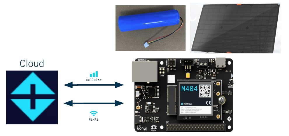
This example shows a real-world, power-optimized setup using the Muon Kit with an M-SoM. The goal: build a resilient solar-powered application using standard components and minimal customization that can last at least one week on battery power alone.

Hardware:
- Muon Kit with M404 SoM (Cellular + Wi-Fi)
- 3250 mAh single-cell LiPo battery (included in kit)
- 30 W solar panel, connected to VIN
Firmware:
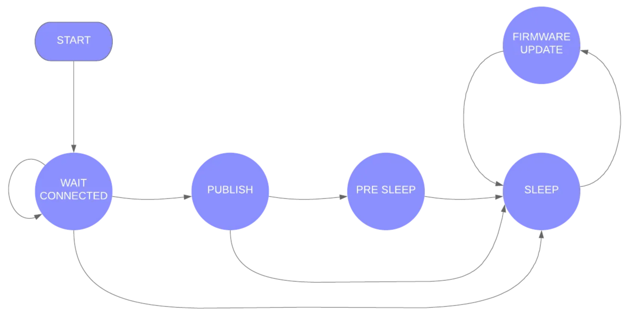
The project firmware leverages the Wake publish sleep example and implements a finite state machine, a reliable way to manage publishing, OTA windows, and sleep transitions. See the GitHub repo for the full firmware.

Key features
- PMIC configuration
Disables 3V3_AUX and sets charge current based on source.
Note: Starting in Device OS 6.3.1, the 3V3_AUX will be automatically disabled when implementing sleep modes. However, if you are using a prior OS version or want to manage it manually, refer to the Muon firmware settings.
// power module hasn't been configured already
// configuration writes value in flash so don't want to overly configure, just once
EEPROM.get(EEPROM_ADDR, powerModuleConfig);
if (powerModuleConfig != PM_FLAG)
{
  Log.info("Configuring Power Module");
  // set power module configuration
  SystemPowerConfiguration conf;
    conf.powerSourceMaxCurrent(1500)    // sets max current from power source (set to max)
      .powerSourceMinVoltage(3880)      // sets min batt voltage
      .batteryChargeCurrent(900)        // sets batt charge current, size based off of solar panel
      .batteryChargeVoltage(4112)       // sets batt charge voltage
      .feature(SystemPowerFeature::PMIC_DETECTION)    // enables PMIC Detection
      .auxiliaryPowerControlPin(PIN_INVALID).interruptPin(PMIC_INTERRUPT_PIN);    // disables 3V3_AUX
  int res = System.setPowerConfiguration(conf);
  Log.info("setPowerConfiguration=%d", res);
  // returns SYSTEM_ERROR_NONE (0) in case of success

  // write flag value to EEPROM
  EEPROM.put(EEPROM_ADDR, PM_FLAG);
  Log.info("Setting PM_FLAG");
}
Because configuration is written in Flash, you need to be careful about how many times you configure it. Therefore, there is a flag written in flash on first configuration (using EEPROM emulation) to ensure the configuration is only written once.
- Battery-aware behavior
Checks SoC and state before connecting to the cloud.
// check battery level and state
delay(5s);                                    // delay before reading from the PMIC, gives the PMIC time to settle before reading
float batterySoc = System.batteryCharge();    // read the battery SoC from PMIC
int batteryState = System.batteryState();     // read the battery state from PMIC
Log.info("Battery state: %s", batteryStates[std::max(0, batteryState)]);
Log.info("Battery charge: %f", batterySoc);

if ((batterySoc >= LOW_BATTERY_THRESHOLD) || ((batteryState == 2))) {
  // It's only necessary to connect to the cloud. Stepping up one layer
  // at a time with Cellular.connect() and wait for Cellular.ready() can
  // be done but there's little advantage to doing so.
  Particle.connect();

  // if device doesn't connect due to connection timeout, go back to sleep
  waitFor(Particle.connected, 60000);
  if (!Particle.connected()) {
    Log.info("Fail to connect, connection timeout");

    // Prepare for sleep
    SystemSleepConfiguration config;
    config.mode(SystemSleepMode::ULTRA_LOW_POWER)   // set sleep to ULP
      .gpio(PMIC_INTERRUPT_PIN, FALLING)            // wake of PMIC _INT (toggle low when changed noted)
      .duration(sleepTime);                         // wake on defined interval
    System.sleep(config);

    // to mimic hibernation mode, reset device (re-run setup())
    System.reset();   // reset the system, ULP continues execution where it left off
  }

  // set the stateTime variable to the current millis() time
  stateTime = millis();

}

// go back to sleep
else  {
  Log.info("Fail to connect due to Battery charge: %f", batterySoc);

  // Prepare for sleep
  SystemSleepConfiguration config;
  config.mode(SystemSleepMode::ULTRA_LOW_POWER)   // set sleep to ULP
    .gpio(PMIC_INTERRUPT_PIN, FALLING)            // wake of PMIC _INT (toggle low when changed noted)
    .duration(sleepTime);                         // wake on defined interval
  System.sleep(config);

  // to mimic hibernation mode, reset device (re-run setup())
  System.reset();   // reset the system, ULP continues execution where it left off
}
- ULP mode sleep logic
Wakes hourly or when VIN (power) is detected via PMIC Interrupt, PMIC_INT (A7).
case STATE_SLEEP:
  // check to determine if a firmware update has been detected
  if (firmwareUpdateInProgress) {
    Log.info("firmware update detected");
    state = STATE_FIRMWARE_UPDATE;
    stateTime = millis();
    // break from switch statement
    break;
  }
  // go to sleep
  Log.info("going to sleep for %ld seconds", (long) sleepTime.count());
  {

     // gracefully disconnect from network, required when using SEMI_AUTOMATIC mode
     Network.disconnect();
     Network.off();

     // Prepare for sleep
     SystemSleepConfiguration config;
     config.mode(SystemSleepMode::ULTRA_LOW_POWER)   // set sleep to ULP
       .gpio(PMIC_INTERRUPT_PIN, FALLING)            // wake of PMIC _INT (toggle low when changed noted)
       .duration(sleepTime);                         // wake on defined interval
     System.sleep(config);

     // to mimic hibernation mode, reset device (re-run setup())
     System.reset();   // reset the system, ULP continues execution where it left off

   }
   // This is never reached; when the device wakes from sleep it will start over with setup() due to System.reset()
   break;
- Adaptive state logic
While VIN is present and SoC > 15%, publishes every 15 minutes, otherwise, go to sleep.
case STATE_PUBLISH:
  // read the battery state and SoC from PMIC
  batteryState = System.batteryState();
  batterySoc = System.batteryCharge();
  Log.info("Battery state: %s", batteryStates[std::max(0, batteryState)]);
  Log.info("Battery charge: %f", batterySoc);
  //continue to publish value while charging or charged @ PUBLISH_PERIOD interval
  if ((batterySoc >= LOW_BATTERY_THRESHOLD) && ((batteryState == 2) || (batteryState == 3))) {
    if ((lastPublish == 0) || (millis() - lastPublish >= PUBLISH_PERIOD.count())) {
      lastPublish = millis();
      state = STATE_WAIT_CONNECTED;    // go back to STATE_WAIT_CONNECTED
      publish_status();
    }
  }
  // go to sleep after publish
  else  {
    // read the latest battery SoC from PMIC
    batterySoc = System.batteryCharge();
    Log.info("Battery charge: %f", batterySoc);
    // check to confirm batt level is above
    if (batterySoc >= LOW_BATTERY_THRESHOLD) {
      publish_status();
    }
    else {
      Log.info("Fail to publish due to Battery charge: %f", batterySoc);
    }
    // check to put device into  STATE_PRE_SLEEP
    if (millis() - stateTime < cloudMinTime.count()) {
      Log.info("waiting %lu ms before sleeping", (unsigned long)(cloudMinTime.count() - (millis() - stateTime)));
      state = STATE_PRE_SLEEP;
    }
    // cloudMinTime has elapsed, go into STATE_SLEEP
    else {
      state = STATE_SLEEP;
    }
  }
  // break from switch statement
  break;
- Typed + Extended publish
Uses new Typed and Extended publish() API introduced in OS 6.3.0 for reliable message delivery with timeouts. The event or publish name is dictated whether the device will remain in an active state, "Powered," or whether the device will go to sleep, "Sleep."
// function for publishing the status of the device
void publish_status() {

  // local variables
  int powerSource = System.powerSource();
  int batteryState = System.batteryState();
  float batterySoc = System.batteryCharge();

  // set objects within json
  particle::Variant obj;
  obj.set("Battery charge %:", batterySoc);
  obj.set("Battery state:", batteryStates[std::max(0, batteryState)]);
  obj.set("Power source:", powerSources[std::max(0, powerSource)]);

  // set event name, data, and publish()
  if (state == STATE_WAIT_CONNECTED){
    event.name("Powered");
  }
  else  {
    event.name("Sleep");
  }
  event.data(obj);
  Particle.publish(event);
  Log.info("publishing %s", obj.toJSON().c_str());

  // Wait while sending
  waitForNot(event.isSending, 60000);

  // logic for determining success/failure of publish()
  if (event.isSent()) {
    Log.info("publish succeeded");
    event.clear();
  }
  else
  if (!event.isOk()) {
    Log.info("publish failed error=%d", event.error());
    event.clear();
  }
}
Summary
Generation 4 devices deliver faster processors, more memory, and multi-radios products, but that performance comes with a higher power budget. For battery and solar-powered applications, power management becomes essential.
By combining firmware sleep techniques with smart hardware design, disabling unused peripherals, choosing the right battery, and leveraging built-in PMIC features, you can build robust, low-power applications that make full use of the Generation 4 devices without compromising on energy efficiency.
Ready to get started?
Order your Muon from the store.
