Creating an inventory management system with Particle


Ready to build your IoT product?
Create your Particle account and get access to:
- Discounted IoT devices
- Device management console
- Developer guides and resources
Background
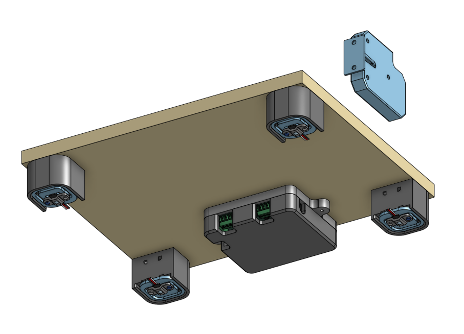
Wireless connectivity can enable automation of traditionally manual tasks such as taking inventory of stock. Rather than relying on periodic manual records, we can deploy a Particle wireless module to keep track of stock levels in a system — a very similar approach to Amazon’s (now discontinued) smart shelf. This post will discuss how to design and deploy an inventory management system using a Particle M-SoM combined with a custom carrier PCB.
Overview
We’ll walk through the hardware design, firmware, and Particle Cloud implementation. The next logical step in the build would be to develop a web dashboard for the user so they can interact with the system, but that will be out of scope for this post.
The carrier board will have a number of requirements:
- Provide all of the necessary components to interface with the Particle module.
- Monitor the temperature of the system.
- Drive a locking solenoid as well as keep track of the solenoid’s current state.
- Read load cell data to estimate current inventory level.
The Particle Cloud implementation should have the following features:
- Lock and unlock the system from a triggered event.
- Keep constant track of the existing inventory, temperature, the lock’s state.
- Calibrate the system given the weight of a single unit.
- Zero the system with no units.
Hardware
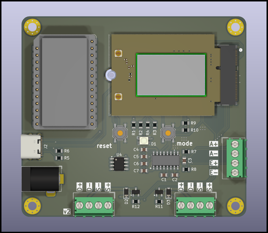
Taking into consideration the hardware requirements we can consider the following major electrical components:
| M.2 connector | Interface for the Particle SoM |
|---|---|
| USB-C connector | To program the SoM |
| Barrel jack connector | 12V DC power (power to the SoM and locking solenoid) |
| LM35 temperature sensor | Monitor system temperature |
| PM-DC | Particle power module for SoM |
| NAU7802 24-bit ADC | Read load cell data |
| AO3406 MOSFET | Switching power for the locking solenoid |
Wiring up all of the supporting circuitry for these components yields the following schematic:


After routing the components for the PCB, we’re ready to ship it off for fabrication.
Firmware
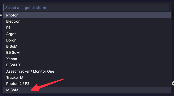
The firmware should be pretty straight forward. Start by creating a new project with the Particle Workbench and configuring it for an M-SoM.

center
Next, we can get started on our driver code. Luckily, we can use the Sparkfun NAU7802 driver in our source code directly. Do this by copying the .cpp and the .h file into an nau7802 folder inside of the src directory of our project. I chose to rename the files nau7802.cpp and nau7802.h for simplicity, but this is optional.
We will also create a light wrapper on top of the nau7802 driver code by creating a src/scale folder with scale.cpp and scale.h.
In scale.h add the following code:
#include "Particle.h"
#include "../nau7802/nau7802.h"

#define LOCATION_CALIBRATION_FACTOR 0

#define AVG_SIZE 25

int32_t readScale();
int getInventoryCount(long countsPerUnit);
void initializeScale();
void zeroScale();
In scale.cpp, add the following:
#include "scale.h"

NAU7802 scale;
int32_t latestReading = 0;

// Create an array to take average of weights. This helps smooth out jitter.
int32_t avgReadings[AVG_SIZE];
byte avgReadingIdx = 0;

int32_t readScale()
{
    if (scale.available() == true)
    {
        int32_t currentReading = scale.getAverage(10, 2000);

        avgReadings[avgReadingIdx++] = currentReading;
        if (avgReadingIdx == AVG_SIZE)
            avgReadingIdx = 0;

        int32_t avgReading = 0;
        for (int x = 0; x < AVG_SIZE; x++)
            avgReading += avgReadings[x];
        double avgCalc = (double)(avgReading) / AVG_SIZE;
        latestReading = (int32_t)(avgCalc);
    }
    return latestReading;
}

int getInventoryCount(long countsPerUnit)
{
    return (int32_t)(latestReading / (double)(countsPerUnit) + 0.5);
}

void zeroScale()
{
    scale.calibrateAFE(NAU7802_CALMOD_OFFSET);
    delay(50);

    for (int x = 0; x < AVG_SIZE; x++)
    {
        int32_t tmpReading = scale.getReading();
        avgReadings[x] = tmpReading;
    }
}

void initializeScale()
{
    if (scale.begin() == false)
    {
        Log.info("Scale not detected. Please check wiring. Freezing...");
    }
    scale.setSampleRate(NAU7802_SPS_80); // Set sample rate: 10, 20, 40, 80 or 320
    scale.setGain(NAU7802_GAIN_32);      // Gain can be set to 1, 2, 4, 8, 16, 32, 64, or 128.
    scale.setLDO(NAU7802_LDO_3V0);       // Set LDO voltage. 3.0V is the best choice for Qwiic
    scale.calibrateAFE(NAU7802_CALMOD_INTERNAL);

    delay(500);
    // Take 10 readings to flush out readings
    for (uint8_t i = 0; i < 10; i++)
    {
        while (!scale.available())
            delay(1);
        scale.getReading();
    }
    zeroScale();
}
I’m using a rolling average of 25 measurements in order to minimize the noise in my system. The system tries to zero itself on each reboot, so it is important to leave the scale unloaded when powering it up. getInventoryCount tries get the nearest whole number inventory state during the calculation.
With the scale sorted out, we can move on to implementing the temperature measurement. Create a src/temp/temp.cpp and src/temp/temp.h file. In temp.h, add the following code:
#include "Particle.h"

#define TEMP_ANALOG A0

float readTemperature();
void initializeTemp();
In temp.cpp, add the following:
#include "temp.h"

const float scalingFactor = 0.01;

float readTemperature()
{
    float total = 0.0;
    uint8_t samplesAcquired = 0;
    uint8_t averageAmount = 64;

    while (1)
    {
        float voltage = (analogRead(TEMP_ANALOG) * 3.3) / 4095.0;
        float temp = voltage / scalingFactor;
        total += temp;
        if (++samplesAcquired == averageAmount)
            break; // All done

        delay(1);
    }
    total /= averageAmount;
    return total;
}

void initializeTemp()
{
    pinMode(TEMP_ANALOG, INPUT);
}
The LM35 temperature sensor generates an analog voltage based on the current temperature. Each 10 millivolts correlates to 1 degree Celsius. We take a number of temperature samples and average them to get our temperature value in degrees C.
Finally, we can pull our drivers together in main.cpp. Add the following code:
#include "Particle.h"
#include "scale/scale.h"
#include "temp/temp.h"

SYSTEM_MODE(AUTOMATIC);

#define UNLOCK_DELAY 500
#define SOL_STATE_1 D4
#define SOL_SIG_1 D23

static int32_t scaleReading = 0;
static int inventoryCount = 0;
static float temperature = 0;

long unsigned int statusInterval = 15 * 60 * 1000;
static unsigned long lastStatusTime = 0;
static long countsPerUnit = 1;

static volatile bool didUnlock = false;
static volatile bool shouldCalibrate = false;
static volatile bool shouldTare = false;
static volatile unsigned long unlockTime = 0;

Ledger statusLedger;

SerialLogHandler logHandler(
    LOG_LEVEL_NONE, // Default logging level for all categories
    {
        {"app", LOG_LEVEL_ALL} // Only enable all log levels for the application
    });

int tare(String command)
{
  shouldTare = true;
  return 0;
}

int calibrate(String command)
{
  shouldCalibrate = true;
  return 0;
}

int unlock(String command)
{
  digitalWrite(SOL_SIG_1, 1);
  didUnlock = true;
  unlockTime = millis();
  Log.info("Unlocking!");
  return 0;
}

void setup()
{
  Serial.begin(115200);

  pinMode(SOL_SIG_1, OUTPUT);
  pinMode(SOL_STATE_1, INPUT_PULLUP);

  Particle.function("tare", tare);
  Particle.function("calibrate", calibrate);
  Particle.function("unlock", unlock);

  statusLedger = Particle.ledger("thingio-status-d2c");

  EEPROM.get(LOCATION_CALIBRATION_FACTOR, countsPerUnit);
  if (countsPerUnit == 0x7FFFFFFF)
  {
    countsPerUnit = 1;
  }
  Log.info("Got %ld counts per unit", countsPerUnit);
  initializeScale();
}

void loop()
{
  if (Particle.connected())
  {
    Variant data;

    scaleReading = readScale();
    inventoryCount = getInventoryCount(countsPerUnit);
    temperature = readTemperature();

    if (lastStatusTime == 0 || ((millis() - lastStatusTime) >= statusInterval))
    {
      if (Time.isValid())
      {
        data.set("time", Time.format(TIME_FORMAT_ISO8601_FULL));
      }
      data.set("raw", scaleReading);
      data.set("inventory", inventoryCount);
      data.set("temperature", temperature);
      data.set("locked", !digitalRead(SOL_STATE_1));
      data.set("counts_per_unit", countsPerUnit);

      Log.info("%s", data.toJSON().c_str());
      statusLedger.set(data, particle::Ledger::MERGE);

      lastStatusTime = millis();
    }
    if (didUnlock && ((millis() - unlockTime) >= UNLOCK_DELAY))
    {
      digitalWrite(SOL_SIG_1, 0);
      didUnlock = false;
      lastStatusTime = 0; // Force a system status update
      Log.info("Reset lock pin");
    }
    if (shouldCalibrate)
    {
      countsPerUnit = readScale();
      EEPROM.put(LOCATION_CALIBRATION_FACTOR, countsPerUnit);

      shouldCalibrate = false;
      Log.info("Calibrated: %ld", countsPerUnit);
    }
    if (shouldTare)
    {
      zeroScale();
      shouldTare = false;
      Log.info("Zero'd scale");
    }
  }
}
The system initializes the temperature sensor, scale subsystem, solenoid driver pins, and the thingio-status-d2c Ledger. If the EEPROM has information about the previous calibration factor, then it updates the countsPerUnit variable.
The loop waits until the Particle Cloud is connected before reporting the system state to the Ledger every 15 minutes (statusInterval). Notice that ledger.set uses the merge set mode, which will restrict the update to only values that have changed.
We also set up some cloud functions for tare, calibrate, and unlock. It’s important to not put blocking logic in the callback functions, so they simply set a flag to be processed by the loop during its next pass through.
Particle Cloud configuration
In the Particle Console, you only need to set up the Ledger instance, which the firmware will periodically update. We can do this by navigating to the Cloud services > Ledger page. Here select “Create new Ledger.”

Our new Ledger should be a “Device to Cloud Ledger.”
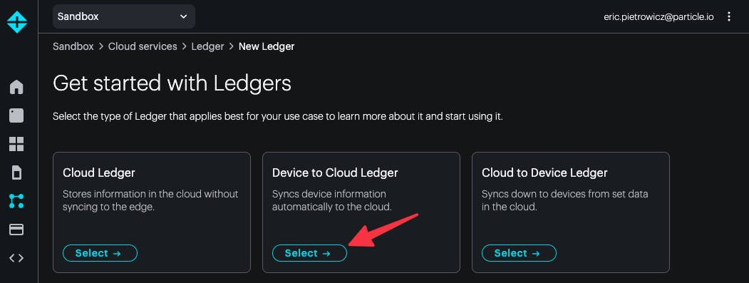
Here, make sure the Ledger name matching the name you defined in your firmware. The description field can be anything. In this example, we’ve chosen thingio-status-d2c.
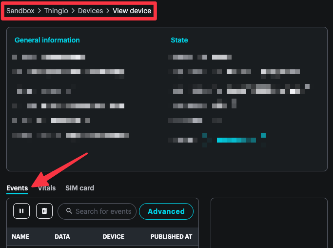
With your new Ledger created we can flash and test the firmware. With the board powered up, confirm that events are being published via the device details page:
center
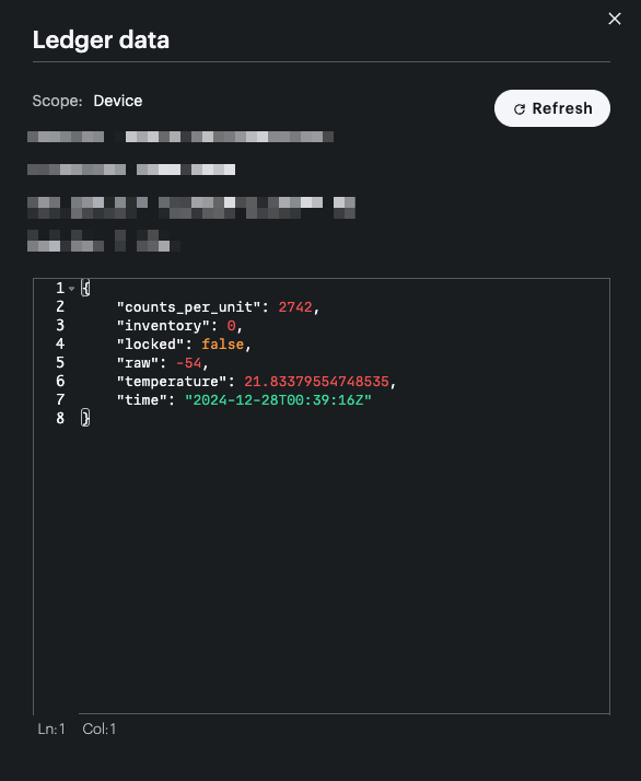
When you have confirmed that your device is publishing as expected, navigate back to the Ledger instance and check its latest instance.

center
The instance reflects the latest state of our system. The ability to get this information at any time, no matter if the device is offline or not currently publishing is strongest feature of this type of Ledger. You might query this Ledger instance via a web or mobile app to display the device state to the user without having to have your own database configured to capture the event stream.
Conclusion
We explored an example configuration for how you might develop an inventory management system using a custom PCB and a Particle SoM. This application doesn’t necessarily require any additional cloud infrastructure outside of Particle’s tooling. You could easily develop a web-based frontend that handles the lock / unlock cloud function and queries the Ledger instance for the current device state. As shown, leaning on Particle’s tooling allows you to dramatically decrease the development effort.
Ready to get started?
Order your M-SoM from the store.
